Robotics · 4 min read
Building a robotic arm to tidy my desk — part 1
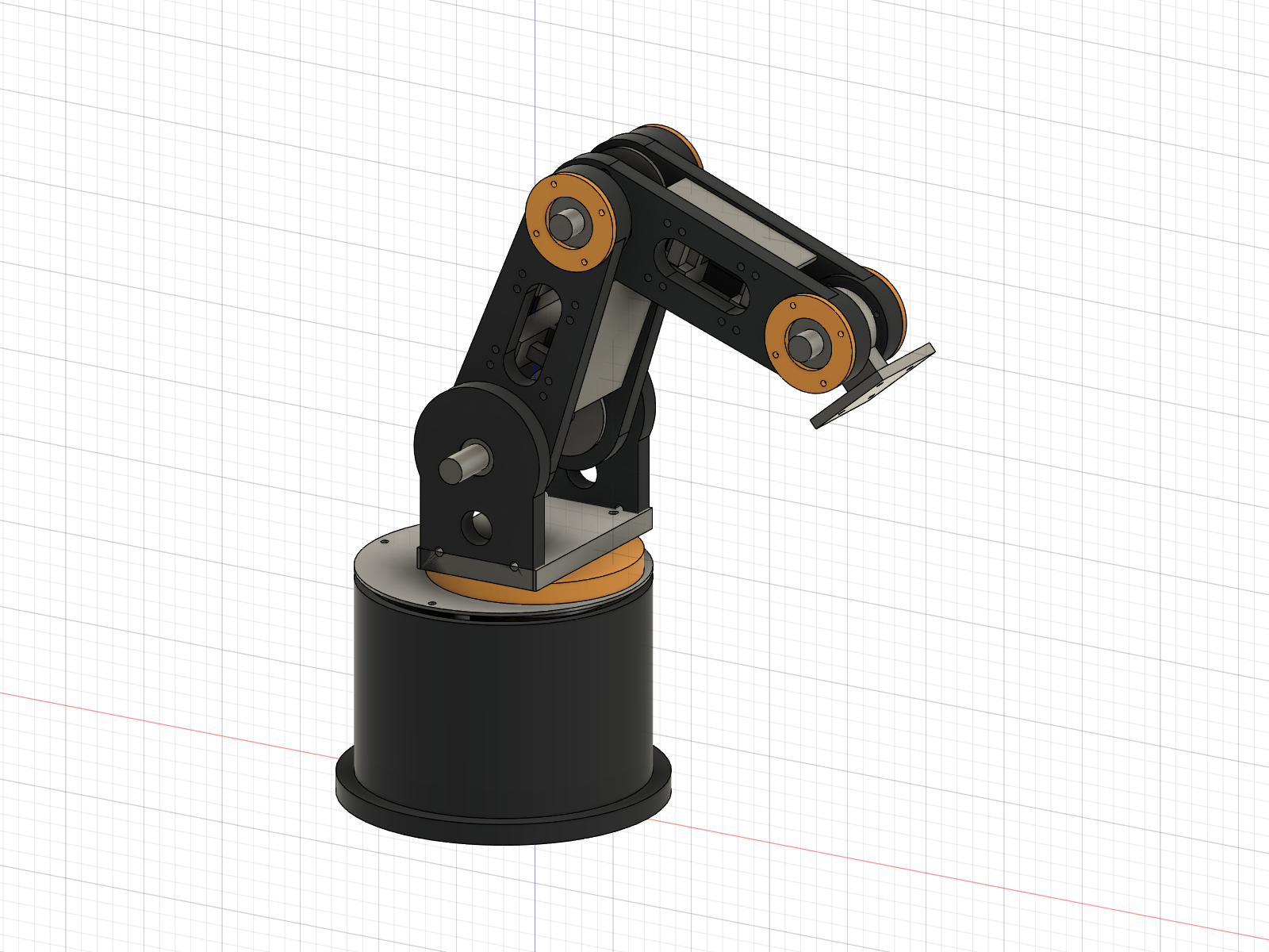
By the time I finish work, there are usually pens, pencils, and other small things scattered across my desk. I started wondering whether I could build an arm that would put them back in their places.
I’d already been experimenting with microcontrollers, stepper motors, and 3D printing. This gave me a reason to bring them together. The job sounded small enough: reach over, pick something up, put it down somewhere else. Working out how to do that reliably has been most of the project.
This is the first part of that build: the design, the software, and the problems I’m working through. A robot that can clean the desk on its own is still the goal.
Choosing the shape
My desk is 120 × 60 cm. I first considered a SCARA-style arm on a linear rail so it could travel across more of that space. The extra reach was appealing, but the rail also meant another mechanism to build, align, and control.
I settled on an articulated arm with a fixed base and three rotating axes. The base turns it left and right, the shoulder raises the first link, and the elbow changes how far it reaches. A small servo operates the gripper.
I’m using Fusion 360 to work through the geometry, motor mounts, and parts I can print. The difficult bits are often the connections: how two pieces rotate freely while staying firmly attached to each other.
Building around the parts I had
I already had three NEMA 17 stepper motors, GT2 belts and pulleys, an ESP32, and a 3D printer. I wanted to work with those parts rather than start with a ready-made arm.
One thing that changed my design was separating the job of moving a joint from the job of supporting it. The motor supplies torque; shafts and bearings need to carry the mechanical load. Hanging the arm directly off a motor shaft wasn’t the solution I wanted.
The joints use belt reduction: a smaller pulley on the motor drives a larger one at the joint. That gives up speed for more output torque and lets me place the motor away from the joint’s axis. Bearings can then support the rotating assembly independently.
Reach makes this harder. A longer arm can cover more desk, but it also asks more of the shoulder when extended. I’m trying to keep the printed structure light without making it too flexible to position repeatably.
Where the software fits
The software is the part I was most eager to get into. It also comes with an awkward difference from the backend work I’m used to: sending a valid command doesn’t tell me whether the arm actually got where I wanted it to go.
I’m separating the control into two layers. The ESP32 handles the motor drivers, movement signals, servo gripper, and basic motion limits. That keeps the step timing and direct control close to the hardware.
For the higher-level side, I’ve been exploring ROS 2: how to represent joint states, pass movement requests between components, and organize motion planning. The idea is for that layer to request a movement while the ESP32 turns it into motor commands. I still need a clear interface between the two, especially for debugging when the requested movement and the physical result don’t match.
Planned control flow
ROS 2 being explored
Joint states & motion planning
ESP32
Step timing, motion limits & gripper control
Motor drivers
3 × NEMA 17
GT2 belt reduction
Base · shoulder · elbow
Servo
Gripper
Pick up & release
Shafts and bearings carry the joint loads.
From a spot on the desk to joint angles
Eventually, I want to give the arm a position to reach instead of a sequence of motor steps I’ve recorded by hand. That means working through the kinematics.
Forward kinematics tells me where the gripper should be for a set of joint angles. Inverse kinematics works the other way: starting with a target position and finding angles that could reach it. Some positions have more than one possible configuration; others are outside the arm’s reach altogether.
Getting an answer from the maths is only part of it. I need the physical arm to follow that answer consistently.
The small things that aren’t small
A commanded number of steps isn’t a measurement of where the arm ended up. Missed steps, play in the belts or joints, flexible parts, and calibration errors can all add up. Reliable homing and repeatable movement have to come before a clever cleaning routine.
Then there’s the pen itself. It’s narrow, round, and lying flat against the desk. The gripper needs an approach that lets it get hold of the pen without simply nudging it away. Being able to move the arm accurately won’t, on its own, solve that.
Next: putting it together
The next part is the physical build: printing the components, assembling the joints, fitting the motors, wiring the electronics, and testing what actually moves. I’ll cover that in part 2.
For now, I want dependable pick-and-place movements. Camera-based object detection and more autonomous planning can come after that. There’s enough to learn just getting the same object to the same place twice.